We use cookies to make your experience better. To comply with the new e-Privacy directive, we need to ask for your consent to set the cookies. Learn more.

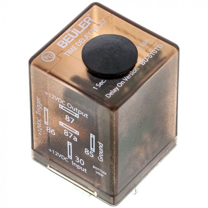
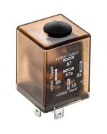
Beuler BU510TD 12 VDC Automotive 5-Pin SPDT Time Delay Relay with adjustable timing - Delay On
$22.99
In stock
SKU
BU510TD
- Buy 50 for $21.99 each and save 4%
- Buy 100 for $20.99 each and save 9%

Expert Knowledge
Talk to a specialist
- Standard automotive style relay
- Adjustable time delay on with 1 seconds to 1 minutes timer with internal potentiometer
- 20 amp / 30 amp rated contacts
- SPDT - Single pole Dual throw
- Low 1volt (1k Ohm) trigger voltage
Unit includes: 12 volt time delay relay
Beuler BU510TD 12 VDC Automotive 5-Pin SPST Time Delay Relay with adjustable timing
The Beuler BU510TD is a versatile delay-on time relay designed to activate a circuit after a preset delay once +12 volts is applied to the trigger input. With an adjustable timing range, the BU510TD gives you precise control over when accessories turn on, making it ideal for automotive, marine, security, and industrial applications. Common uses include delayed amplifier turn-on, secret compartments, electronic safes, cooling fans, lighting, and other custom control circuits. Built with a standard Bosch-style 5-pin configuration, the relay features SPDT (Single Pole, Double Throw) contacts rated for 30 amps continuous, low 120mA coil current draw at 12VDC, and an easy-to-wire design that integrates seamlessly into new or existing electrical systems.
-
Features:
- Standard automotive style relay
- No mounting tab
- Delay On Version
- Requires the application of power for the relay to wait to latch (Requires the removal of 12 volts on the coil to reset timer, with constant 12 volts relay is un-latched like an ordinary 5-pin relay)
- Low 1volt (1k Ohm) trigger voltage
- Adjustable time latching from 1 seconds to 1 minute with internal potentiometer, the time delay extends or delays the activation of the relay
- Built in diode to stop timer feedback issues
- Momentary pulse to trigger latching
- Internal green LED to indicate status
- Non-removable cap
- 20 amp / 30 amp rated contacts
- SPDT - Single pole Dual throw
- 12 Vdc rated coil with minimum 8 volt to trigger
- Power consumption @ 12Vdc 120 mA
- Idle current draw 2 mA
- Conventional 87, 87a, 30, 86, and 85 pin locations
- SPDT Change Over NC/NO (form C)
- Compatible with most insulated and non insulated terminals and relay sockets
- Dimensions 1-1/4" (W) x 1-1/4" (D) x 2" (H) with terminals
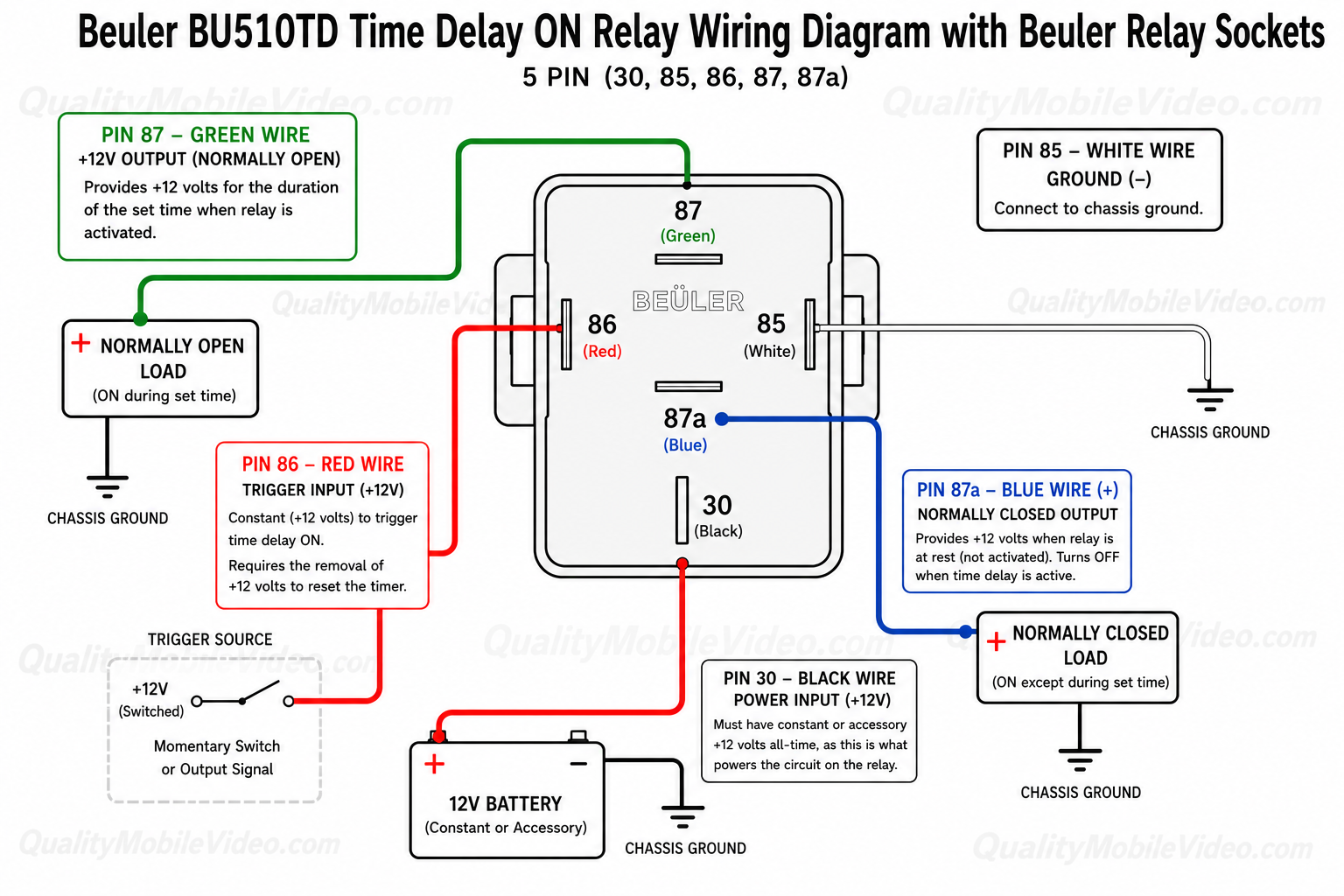
- Pin configuration:
- Pin 30 - Must have constant or accessory 12 volts all-time, as this is what powers the circuit on the relay
- Pin 85 - Ground
- Pin 86 - Constant (+12 volts) to trigger time delay on (Requires the removal of +12 volts to reset the timer)
- Pin 87a - +12 volt output (Normally closed contact - on except when time delay is active)
- Pin 87 - +12 volt output (Normally open contact - on for duration of set time)
- Uses:
- Low voltage trigger: input will trigger with as little as 1 volt (Constant or pulsed)
- Momentary pulse to timed latch: use a momentary switch to trigger for a short duration (up to 3 minutes)
- Voltage inverter: temporarily reverse the polarity to a drain (requires additional relays
- How the unit functions
- Momentary pulse: 12 volt positive momentary pulse connected to Pin 86, once pulse goes to zero the relay will trigger for preset timing
- Constant input: 12 volt positive constant connected to Pin 86, once constant goes goes to zero the relay will trigger for preset timing
- Pin configuration (When using BRS14E or BRS12E):
| Pin | Beuler Relay Socket Wire Color | Function | Description |
|---|---|---|---|
| 30 | Black | Power Input (+12V) | Must be connected to a constant or accessory +12V source at all times. This supplies operating power to the relay. |
| 85 | White | Ground (-) | Connect directly to chassis ground or battery negative. |
| 86 | Red | Trigger Input (+12V) | Apply a constant +12V signal to begin the delay-on timer. The +12V trigger must be removed before the timer can be activated again. |
| 87a | Blue | Normally Closed Output (+12V) | Provides +12V while the relay is at rest. Output turns OFF whenever the time delay is active. |
| 87 | Green | Normally Open Output (+12V) | Provides +12V after the programmed delay has elapsed and remains ON for the duration of the timing cycle. |
| Manufacturer | Beuler |
|---|---|
| Part Number | BU510TD |
| Operation Voltage | 8-15 Volt DC |
| Relay type | Time delay relay |
| Current capacity | 20 Amp / 30 Amp |
| Pole switching type | SPDT (Single pole Dual throw) |
| Tab type | No Tab |
| Waterproof ingress protection | None |
| Warranty | 1 Year |
| California Proposition 65 | |
| Return period | 30 days |
| Exchange period | 30 days |
Write Your Own Review
Relay Pinout Diagrams Explained
A relay pinout diagram shows the function of each terminal (pin) on a relay and how the internal connections work. It helps you wire the relay correctly for your project.
1. Basic Relay Anatomy
Most automotive relays have two main parts:
- Coil – An electromagnet that switches the relay on/off (low current side)
- Switch Contacts – The high-current switch that turns your accessory on/off
2. Most Common Automotive Relay: 5-Pin SPDT
This is the standard relay type used with sockets like BRSCN, BRSPC, BRSS, etc.
| Pin | Name | Function |
|---|---|---|
| 30 | Common | Power input (goes to the load) |
| 87 | Normally Open (NO) | Closed when relay is energized (ON) |
| 87a | Normally Closed (NC) | Closed when relay is de-energized (OFF) |
| 85 | Coil Ground | Negative side of coil |
| 86 | Coil Positive | Positive side of coil (+12V trigger) |
Visual Pinout Diagram
          87
          │
   87a ───┼─── 30
          │
         [Relay]

   85 ───────── 86
How It Works:
- No power to 85/86 → Current flows between 30 and 87a
- +12V applied to 85/86 → Coil energizes → Current flows between 30 and 87
4. How to Read a Relay Pinout Diagram
Most relay pinout diagrams include the following elements:
- A box or outline representing the relay body
- Pin numbers clearly labeled next to each terminal
- Internal connections shown with lines or dotted lines
- Coil symbol (usually a rectangle or spring-like coil)
- Switch contacts shown with an arrow indicating movement when the relay is energized
Example Relay Pinout Diagram:
       87          30
        │           │
        └──────┬────┘
               │
             ┌──┐     ← Moving Contact
             └──┘
            /     \
          87a      (Switches when coil is energized)

    85 ───────────── 86
          Coil
Understanding the Symbols:
- 30 — Common terminal (input power)
- 87 — Normally Open (NO) contact
- 87a — Normally Closed (NC) contact
- 85 & 86 — Coil terminals (control side)
When the relay coil is energized (pins 85/86 powered), the internal switch moves from 87a to 87.
Quick Wiring Examples (5-Pin Relay)
1. Basic On/Off Circuit (Most Common)
Used for lights, fans, fuel pumps, horns, etc.
- 86 → Switched +12V (from switch, toggle, or ECU output)
- 85 → Ground (or switched ground)
- 30 → Constant +12V Power (from battery or fuse box)
- 87 → Output to Accessory (lights, fan, etc.)
- 87a → Not used (leave disconnected)
2. Changeover / Dual Circuit Setup
Use both 87 and 87a when you need to switch between two different circuits.
- 30 → Input Power
- 87 → Circuit A (ON when relay is energized)
- 87a → Circuit B (ON when relay is OFF)
- 85 & 86 → Coil control
3. Typical Pin Connections Summary
| Pin | Connection | Typical Wire Color | Purpose |
|---|---|---|---|
| 30 | Constant +12V | Black (BRS14E & BRS12E) | Power Input |
| 87 | To Accessory | Green (BRS14E & BRS12E) | Power Output (ON) |
| 87a | Optional 2nd Circuit | Blue (BRS14E & BRS12E) | Power Output (OFF) |
| 85 | Ground | White (BRS14E & BRS12E) | Coil Negative |
| 86 | Switched +12V | Red (BRS14E & BRS12E) | Coil Positive |
Tip: Always use a fused power source on pin 30 for safety.
Basic 5-Pin Relay Wiring Harness
Battery +12V ──► [Fuse] ──► Pin 30 (Common)

Pin 87 ──► Accessory (Lights / Fan / Pump / Amp etc.)

Pin 86 ──► Switched +12V Trigger
               (from switch, headlight wire, remote turn-on, etc.)

Pin 85 ──► Ground

Pin 87a ──► (Optional - Not used in basic setup)
Recommended Wiring (Empty relay socket or spade connectors (Not BRS14E & BRS12E):
- Pin 30 — Red wire with inline fuse (closest to battery)
- Pin 87 — Red or Blue wire to device
- Pin 86 — White or Pink trigger wire
- Pin 85 — Black ground wire
Dual Output (Changeover) Relay Harness
Pin 30   → Constant +12V (Fused)

Pin 87   → Circuit A (ON when relay activated)
Pin 87a  → Circuit B (ON when relay is off)

Pin 86   → Trigger +12V
Pin 85   → Ground
Customer Questions
Related Products
Check items to add to the cart or


We found other products you might like!
More from Beuler

Who Viewed This Also Viewed