The store will not work correctly when cookies are disabled.
We use cookies to make your experience better.To comply with the new e-Privacy directive, we need to ask for your consent to set the cookies. Learn more.
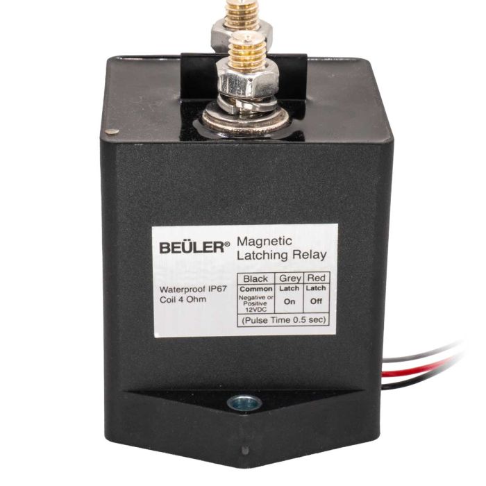
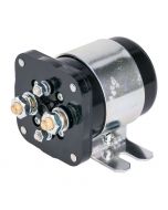
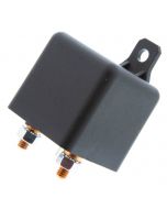
The Beuler Magnetic Latching Relay is a heavy-duty, waterproof power relay designed for high-current applications where eliminating standby power consumption is critical. Using a single-coil magnetic latching design, the relay requires only a brief pulse to switch ON or OFF and draws zero current while latched. Available in 200 Amp and 400 Amp versions, it features an IP67 epoxy-sealed housing for reliable operation in harsh automotive, marine, industrial, and off-road environments, making it ideal for battery disconnects, power management, and high-current switching applications.
Unit includes: High current relay, Mounting hardware, and Instruction manual
Beuler BU400ML 400 Amp Magnetic Latching Relay | Waterproof with Zero Power Draw Relay
Features:
Handles 400-amp continuous current
Durable Epoxy filled weatherproof construction
Designed for 12 volt electrical systems
Relay coil current draw: 0mA - Zero power draw
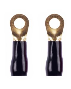
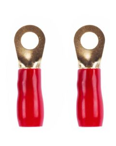
Bolt style terminals for easy connections to ring type terminals
A must for multi-battery systems, allows for longer battery life and control over which battery is being used
Great for isolating a second battery making it dedicated to the stereo system
Does not create a voltage drop to the second battery like conventional isolators
Duty cycle: 100,000 cycles
Waterproof IP67
Wiring:
(3) Wire connection
Black wire - (Common) negative or positive 12 Volts DC
Gray wire - Latch on
Red wire - Latch off
Coil:
Coil pulse time 0.5 sec/1.6A
Coil resistance 7 Ohm
Dimensions:
60mm (W) x 78mm (D) x 88mm (H) Including base and terminals
2-1/4 (W) x 3-1/16 (D) x 3-1/2" (H) Including base and terminals
Warning:This product can expose you to
chemicals including lead, which is [are] known to
the State of California to cause cancer or birth
defects or other reproductive harm. For more
information go to www.P65Warnings.ca.gov.
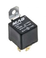
A relay pinout diagram shows the function of each terminal (pin) on a relay and how the internal connections work. It helps you wire the relay correctly for your project.
1. Basic Relay Anatomy
Most automotive relays have two main parts:
Coil – An electromagnet that switches the relay on/off (low current side)
Switch Contacts – The high-current switch that turns your accessory on/off
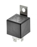
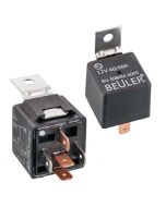
2. Most Common Automotive Relay: 5-Pin SPDT
This is the standard relay type used with sockets like BRSCN, BRSPC, BRSS, etc.
Pin
Name
Function
30
Common
Power input (goes to the load)
87
Normally Open (NO)
Closed when relay is energized (ON)
87a
Normally Closed (NC)
Closed when relay is de-energized (OFF)
85
Coil Ground
Negative side of coil
86
Coil Positive
Positive side of coil (+12V trigger)
Visual Pinout Diagram
          87
          │
   87a ───┼─── 30
          │
         [Relay]

   85 ───────── 86
How It Works:
No power to 85/86 → Current flows between 30 and 87a
+12V applied to 85/86 → Coil energizes → Current flows between 30 and 87
4. How to Read a Relay Pinout Diagram
Most relay pinout diagrams include the following elements:
A box or outline representing the relay body
Pin numbers clearly labeled next to each terminal
Internal connections shown with lines or dotted lines
Coil symbol (usually a rectangle or spring-like coil)
Switch contacts shown with an arrow indicating movement when the relay is energized
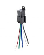
Pin 30 — Red wire with inline fuse (closest to battery)
Pin 87 — Red or Blue wire to device
Pin 86 — White or Pink trigger wire
Pin 85 — Black ground wire
Dual Output (Changeover) Relay Harness
Pin 30   → Constant +12V (Fused)

Pin 87   → Circuit A (ON when relay activated)
Pin 87a  → Circuit B (ON when relay is off)

Pin 86   → Trigger +12V
Pin 85   → Ground