Summer Closeout Up to 70% off select models

Save on select car audio, mobile video, installation gear, and more while supplies last.

Shop Closeout Deals Limited quantities • While supplies last

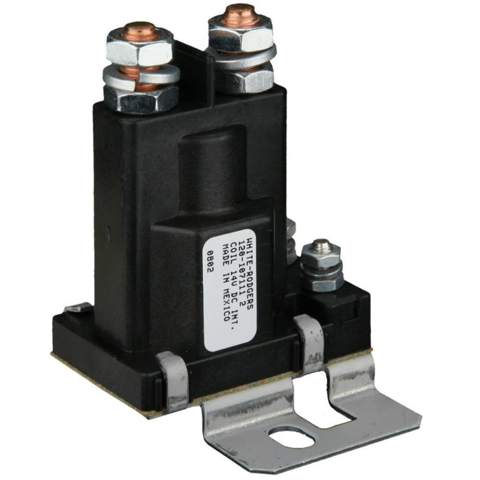
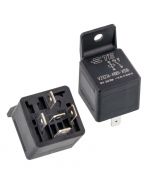
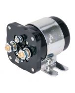
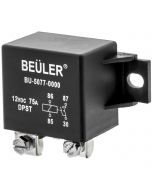
Metra IB80 12 Volt High Current 80 Amp Relay - White Rodgers 120-107112 OEM

$29.99
In stock
SKU
IB80

Key Features

  • Handles 80-amp continuous current and 150-amp surges
  • Durable weatherproof construction
  • Designed for 12 volt electrical systems
  • A must for multi-battery systems, allows for longer battery life and control over which battery is being used
  • Great for isolating a second battery making it dedicated to the stereo system
Unit includes: High current relay, Mounting hardware, and Instruction manual

Metra IB80 12 Volt High Current 80 Amp Relay - White Rodgers 120-107112 OEM

Features:

  • Handles 80-amp continuous current and 150-amp surges
  • Durable weatherproof construction
  • Designed for 12 volt electrical systems
  • Relay coil current draw: 360mA
  • Bolt style terminals for easy connections to ring type terminals
  • A must for multi-battery systems, allows for longer battery life and control over which battery is being used
  • Great for isolating a second battery making it dedicated to the stereo system
  • Does not create a voltage drop to the second battery like conventional isolators
  • Duty cycle: 100,000 cycles

Dimensions:

  • 3-1/4" (H) x 1-3/8" (W) x 2-1/4" (D) Including bracket and terminals
  • More Information
    Manufacturer Chinavasion
    Operation Voltage 12-15 Volt DC
    Relay type High Current
    Current capacity 80 Amp
    Pole switching type SPST (Single pole Single throw)
    Tab type Metal Tab
    Waterproof ingress protection None
    Warranty 1 Year
    California Proposition 65
    California Proposition 65 Warning

    Warning:This product can expose you to chemicals including lead, which is [are] known to the State of California to cause cancer or birth defects or other reproductive harm. For more information go to www.P65Warnings.ca.gov.

    UPC Code 086429129904
    Return period 30 days
    Exchange period 30 days
    Write Your Own Review
    You're reviewing:Metra IB80 12 Volt High Current 80 Amp Relay - White Rodgers 120-107112 OEM
    Your Rating

    Relay Pinout Diagrams Explained

    A relay pinout diagram shows the function of each terminal (pin) on a relay and how the internal connections work. It helps you wire the relay correctly for your project.

    1. Basic Relay Anatomy

    Most automotive relays have two main parts:

    • Coil – An electromagnet that switches the relay on/off (low current side)
    • Switch Contacts – The high-current switch that turns your accessory on/off

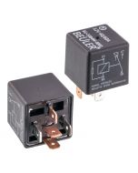
    2. Most Common Automotive Relay: 5-Pin SPDT

    This is the standard relay type used with sockets like BRSCN, BRSPC, BRSS, etc.

    Pin Name Function
    30 Common Power input (goes to the load)
    87 Normally Open (NO) Closed when relay is energized (ON)
    87a Normally Closed (NC) Closed when relay is de-energized (OFF)
    85 Coil Ground Negative side of coil
    86 Coil Positive Positive side of coil (+12V trigger)

    Visual Pinout Diagram

              87
              │
       87a ───┼─── 30
              │
             [Relay]
    
       85 ───────── 86
        

    How It Works:

    • No power to 85/86 → Current flows between 30 and 87a
    • +12V applied to 85/86 → Coil energizes → Current flows between 30 and 87

    4. How to Read a Relay Pinout Diagram

    Most relay pinout diagrams include the following elements:

    • A box or outline representing the relay body
    • Pin numbers clearly labeled next to each terminal
    • Internal connections shown with lines or dotted lines
    • Coil symbol (usually a rectangle or spring-like coil)
    • Switch contacts shown with an arrow indicating movement when the relay is energized

    Example Relay Pinout Diagram:

           87          30
            │           │
            └──────┬────┘
                   │
                 ┌──┐     ← Moving Contact
                 └──┘
                /     \
              87a      (Switches when coil is energized)
    
        85 ───────────── 86
              Coil
        

    Understanding the Symbols:

    • 30 — Common terminal (input power)
    • 87 — Normally Open (NO) contact
    • 87a — Normally Closed (NC) contact
    • 85 & 86 — Coil terminals (control side)

    When the relay coil is energized (pins 85/86 powered), the internal switch moves from 87a to 87.

    Quick Wiring Examples (5-Pin Relay)

    1. Basic On/Off Circuit (Most Common)

    Used for lights, fans, fuel pumps, horns, etc.

    • 86 → Switched +12V (from switch, toggle, or ECU output)
    • 85 → Ground (or switched ground)
    • 30 → Constant +12V Power (from battery or fuse box)
    • 87 → Output to Accessory (lights, fan, etc.)
    • 87a → Not used (leave disconnected)

    2. Changeover / Dual Circuit Setup

    Use both 87 and 87a when you need to switch between two different circuits.

    • 30 → Input Power
    • 87 → Circuit A (ON when relay is energized)
    • 87a → Circuit B (ON when relay is OFF)
    • 85 & 86 → Coil control

    3. Typical Pin Connections Summary

    Pin Connection Typical Wire Color Purpose
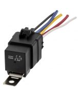
    30 Constant +12V Black (BRS14E & BRS12E) Power Input
    87 To Accessory Green (BRS14E & BRS12E) Power Output (ON)
    87a Optional 2nd Circuit Blue (BRS14E & BRS12E) Power Output (OFF)
    85 Ground White (BRS14E & BRS12E) Coil Negative
    86 Switched +12V Red (BRS14E & BRS12E) Coil Positive

    Tip: Always use a fused power source on pin 30 for safety.

    Basic 5-Pin Relay Wiring Harness

    Battery +12V ──► [Fuse] ──► Pin 30 (Common)
    
    Pin 87 ──► Accessory (Lights / Fan / Pump / Amp etc.)
    
    Pin 86 ──► Switched +12V Trigger
                   (from switch, headlight wire, remote turn-on, etc.)
    
    Pin 85 ──► Ground
    
    Pin 87a ──► (Optional - Not used in basic setup)
        

    Recommended Wiring (Empty relay socket or spade connectors (Not BRS14E & BRS12E):

    • Pin 30 — Red wire with inline fuse (closest to battery)
    • Pin 87 — Red or Blue wire to device
    • Pin 86 — White or Pink trigger wire
    • Pin 85 — Black ground wire

    Dual Output (Changeover) Relay Harness

    Pin 30   → Constant +12V (Fused)
    
    Pin 87   → Circuit A (ON when relay activated)
    Pin 87a  → Circuit B (ON when relay is off)
    
    Pin 86   → Trigger +12V
    Pin 85   → Ground

        
    Customer Questions
    No Questions
    Have a question? Go ahead and ask anything. We are here to help. Please login to ask a product question.
    ©2003-2022 Mobile Electronics Display and Accessories Co., Inc.