The store will not work correctly when cookies are disabled.
We use cookies to make your experience better.To comply with the new e-Privacy directive, we need to ask for your consent to set the cookies. Learn more.
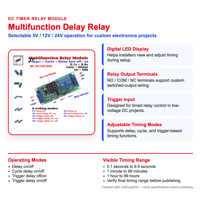
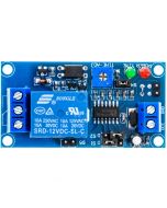
This multifunction DC timer relay module is designed for low-voltage electronics projects that need adjustable delay, cycle, or trigger-based switching. It supports 5V, 12V, and 24V DC applications and includes a digital LED display to help installers view timing settings during setup. Use it for custom automotive electronics, hobby, test-bench, or light-duty relay-control applications where the final wiring and load requirements have been verified first.
Multifunction DC 5V/12V/24V Digital Timer Relay Module
This multifunction DC timer relay module gives installers and electronics hobbyists a compact way to add adjustable timed switching to custom low-voltage projects. The relay supports 12V, and also available in 24V DC operation, multiple delay/cycle/trigger modes, and a digital LED display for setting or viewing timing values. It is best suited for custom automotive electronics, test-bench, lighting, fan, accessory, and other low-current relay-control projects where voltage, load, enclosure, and wiring requirements are verified before installation.
What’s Included
1 multifunction digital timer relay module
Needs verification: printed manual, wiring diagram, mounting hardware, and accessories are not clearly shown as included.
Features
Multi-Voltage DC Operation: Listing states compatibility with 5V, 12V, and 24V DC projects, giving installers flexibility across different low-voltage systems.
Digital LED Display: The onboard display helps users view timing values during setup instead of relying only on fixed jumpers or hidden controls.
Multiple Timing Modes: Visible source image lists delay, cycle delay, trigger delay, and trigger on/off functions for custom switching behavior.
Relay Output Terminals: The board image shows NO, COM, and NC output terminals for common relay-style wiring configurations.
Compact Control Board: The listing describes an 8 x 5 x 3 cm module size, making it easier to place in small project areas after proper protection and mounting are planned.
Warning: This product can expose you to
chemicals including di(2-ethylhexyl)phthalate
(DEHP), which is [are] known to the State of
California to cause cancer or birth defects or other
reproductive harm. For more information go
to www.P65Warnings.ca.gov
A relay pinout diagram shows the function of each terminal (pin) on a relay and how the internal connections work. It helps you wire the relay correctly for your project.
1. Basic Relay Anatomy
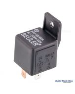
Most automotive relays have two main parts:
Coil – An electromagnet that switches the relay on/off (low current side)
Switch Contacts – The high-current switch that turns your accessory on/off
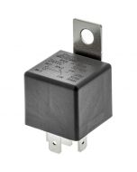
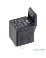
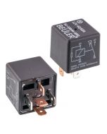
2. Most Common Automotive Relay: 5-Pin SPDT
This is the standard relay type used with sockets like BRSCN, BRSPC, BRSS, etc.
Pin
Name
Function
30
Common
Power input (goes to the load)
87
Normally Open (NO)
Closed when relay is energized (ON)
87a
Normally Closed (NC)
Closed when relay is de-energized (OFF)
85
Coil Ground
Negative side of coil
86
Coil Positive
Positive side of coil (+12V trigger)
Visual Pinout Diagram
          87
          │
   87a ───┼─── 30
          │
         [Relay]

   85 ───────── 86
How It Works:
No power to 85/86 → Current flows between 30 and 87a
+12V applied to 85/86 → Coil energizes → Current flows between 30 and 87
4. How to Read a Relay Pinout Diagram
Most relay pinout diagrams include the following elements:
A box or outline representing the relay body
Pin numbers clearly labeled next to each terminal
Internal connections shown with lines or dotted lines
Coil symbol (usually a rectangle or spring-like coil)
Switch contacts shown with an arrow indicating movement when the relay is energized
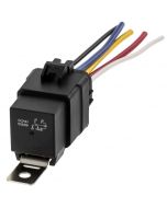
Pin 30 — Red wire with inline fuse (closest to battery)
Pin 87 — Red or Blue wire to device
Pin 86 — White or Pink trigger wire
Pin 85 — Black ground wire
Dual Output (Changeover) Relay Harness
Pin 30   → Constant +12V (Fused)

Pin 87   → Circuit A (ON when relay activated)
Pin 87a  → Circuit B (ON when relay is off)

Pin 86   → Trigger +12V
Pin 85   → Ground