We use cookies to make your experience better. To comply with the new e-Privacy directive, we need to ask for your consent to set the cookies. Learn more.


QMV TDR12V6 6 - 24 VDC SPDT Flip-Flop Latching Relay Module with Low pulse trigger
$10.99
In stock
SKU
TDR12V6

Expert Knowledge
Talk to a specialist
- Relay latches or unlatches with single pulse with NC and NO contacts
- Requires a minimum of 6 volts to function
- 10 amp / 15 amp rated contacts
- SPDT - Single pole Dual throw
- 6 - 24 volt operation
Unit includes: 12 volt latching relay
QMV TDR12V6 6 - 24 VDC SPDT Flip-Flop Latching Relay Module with Low pulse trigger
QMV TDR12V6 6 - 24 VDC SPDT Flip-Flop Latching Relay Module with Low pulse trigger
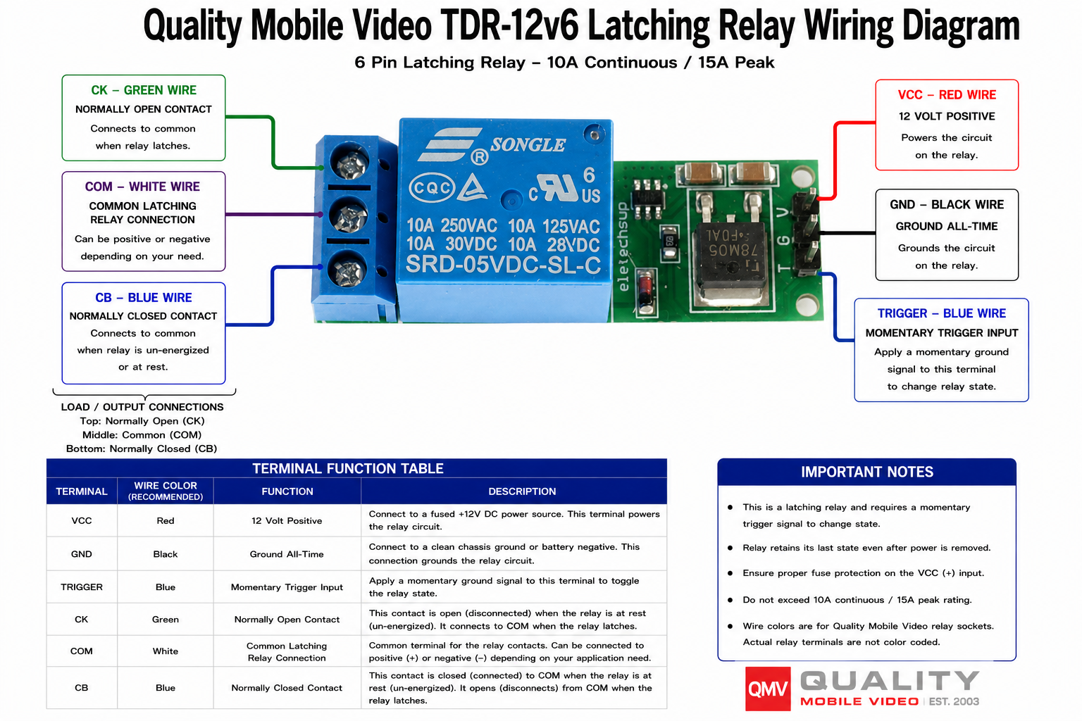
The QMV TDR12V6 is a compact 6-24V DC SPDT flip-flop latching relay module that allows you to control high-current devices with a single low-voltage pulse. One pulse latches the relay on, and the next pulse turns it off, eliminating the need for a maintained switch. Rated for 10 amps continuous (15 amps peak), the TDR12V6 is ideal for automotive electronics, custom switch panels, hidden compartments, linear actuators, lighting, power accessories, and other 12-volt control applications. The module features screw terminal connections for quick installation and a compact design that fits easily into tight spaces.
Features:
- Low voltage latching relay with SPDT flip-flop contacts
- Latches immediately with a single pulse
- Unlatches immediately with a single pulse
- 6-24 volt operation
- 10 amp / 15 amp rated contacts
- SPDT - Single pole Single throw
- 12 Vdc rated coil with minimum 6 volt to trigger
- Power consumption @ 12Vdc 40 mA
- Screw terminals for easy connections up to 14 gauge wire
- Dimensions 5/8" (W) x 1-7/8" (L) x 3/4" (H) with terminals
Contact configuration:
| Terminal | Wire Color | Function | Description |
|---|---|---|---|
| GND | Black | Ground All-Time | Connect the top terminal of the right-side power connector to a clean chassis ground or battery negative. This connection grounds the relay circuit. |
| VCC | Red | 12V Positive | Connect the bottom terminal of the right-side power connector to a fused +12V DC power source. This terminal powers the relay circuit. |
| CK | Green | Normally Open Contact | The top terminal of the left-side output connector is open and disconnected from COM while the relay is at rest. It connects to COM when the relay activates. |
| COM | White | Common Relay Connection | The middle terminal of the left-side output connector is the common contact. It can be connected to positive (+) or negative (-), depending on the application. |
| CB | Blue | Normally Closed Contact | The bottom terminal of the left-side output connector is connected to COM while the relay is unenergized or at rest. It disconnects from COM when the relay activates. |
Contact Rating: 10A continuous / 15A peak
Wire colors are recommended for Quality Mobile Video wiring connections. Actual relay terminals are not color coded.
Uses:
- Switch high current devices with low voltage designer switches
- Create single button flip flop with a push button switch, like a linear actuator
- Simple on/off controller with a pulse
| Manufacturer | Quality Mobile Video |
|---|---|
| Part Number | TDR12V6 |
| Operation Voltage | 12-24 Volt DC |
| Relay type | PCB relay |
| Current capacity | 10 Amp |
| Pole switching type | SPDT (Single pole Dual throw) |
| Tab type | No Tab |
| Waterproof ingress protection | None |
| Warranty | 90 days |
| California Proposition 65 |  Warning: This product can expose you to chemicals including di(2-ethylhexyl)phthalate (DEHP), which is [are] known to the State of California to cause cancer or birth defects or other reproductive harm. For more information go to www.P65Warnings.ca.gov |
| Return period | 30 days |
| Exchange period | 30 days |
Write Your Own Review
Relay Pinout Diagrams Explained
A relay pinout diagram shows the function of each terminal (pin) on a relay and how the internal connections work. It helps you wire the relay correctly for your project.
1. Basic Relay Anatomy
Most automotive relays have two main parts:
- Coil – An electromagnet that switches the relay on/off (low current side)
- Switch Contacts – The high-current switch that turns your accessory on/off
2. Most Common Automotive Relay: 5-Pin SPDT
This is the standard relay type used with sockets like BRSCN, BRSPC, BRSS, etc.
| Pin | Name | Function |
|---|---|---|
| 30 | Common | Power input (goes to the load) |
| 87 | Normally Open (NO) | Closed when relay is energized (ON) |
| 87a | Normally Closed (NC) | Closed when relay is de-energized (OFF) |
| 85 | Coil Ground | Negative side of coil |
| 86 | Coil Positive | Positive side of coil (+12V trigger) |
Visual Pinout Diagram
          87
          │
   87a ───┼─── 30
          │
         [Relay]

   85 ───────── 86
How It Works:
- No power to 85/86 → Current flows between 30 and 87a
- +12V applied to 85/86 → Coil energizes → Current flows between 30 and 87
4. How to Read a Relay Pinout Diagram
Most relay pinout diagrams include the following elements:
- A box or outline representing the relay body
- Pin numbers clearly labeled next to each terminal
- Internal connections shown with lines or dotted lines
- Coil symbol (usually a rectangle or spring-like coil)
- Switch contacts shown with an arrow indicating movement when the relay is energized
Example Relay Pinout Diagram:
       87          30
        │           │
        └──────┬────┘
               │
             ┌──┐     ← Moving Contact
             └──┘
            /     \
          87a      (Switches when coil is energized)

    85 ───────────── 86
          Coil
Understanding the Symbols:
- 30 — Common terminal (input power)
- 87 — Normally Open (NO) contact
- 87a — Normally Closed (NC) contact
- 85 & 86 — Coil terminals (control side)
When the relay coil is energized (pins 85/86 powered), the internal switch moves from 87a to 87.
Quick Wiring Examples (5-Pin Relay)
1. Basic On/Off Circuit (Most Common)
Used for lights, fans, fuel pumps, horns, etc.
- 86 → Switched +12V (from switch, toggle, or ECU output)
- 85 → Ground (or switched ground)
- 30 → Constant +12V Power (from battery or fuse box)
- 87 → Output to Accessory (lights, fan, etc.)
- 87a → Not used (leave disconnected)
2. Changeover / Dual Circuit Setup
Use both 87 and 87a when you need to switch between two different circuits.
- 30 → Input Power
- 87 → Circuit A (ON when relay is energized)
- 87a → Circuit B (ON when relay is OFF)
- 85 & 86 → Coil control
3. Typical Pin Connections Summary
| Pin | Connection | Typical Wire Color | Purpose |
|---|---|---|---|
| 30 | Constant +12V | Black (BRS14E & BRS12E) | Power Input |
| 87 | To Accessory | Green (BRS14E & BRS12E) | Power Output (ON) |
| 87a | Optional 2nd Circuit | Blue (BRS14E & BRS12E) | Power Output (OFF) |
| 85 | Ground | White (BRS14E & BRS12E) | Coil Negative |
| 86 | Switched +12V | Red (BRS14E & BRS12E) | Coil Positive |
Tip: Always use a fused power source on pin 30 for safety.
Basic 5-Pin Relay Wiring Harness
Battery +12V ──► [Fuse] ──► Pin 30 (Common)

Pin 87 ──► Accessory (Lights / Fan / Pump / Amp etc.)

Pin 86 ──► Switched +12V Trigger
               (from switch, headlight wire, remote turn-on, etc.)

Pin 85 ──► Ground

Pin 87a ──► (Optional - Not used in basic setup)
Recommended Wiring (Empty relay socket or spade connectors (Not BRS14E & BRS12E):
- Pin 30 — Red wire with inline fuse (closest to battery)
- Pin 87 — Red or Blue wire to device
- Pin 86 — White or Pink trigger wire
- Pin 85 — Black ground wire
Dual Output (Changeover) Relay Harness
Pin 30   → Constant +12V (Fused)

Pin 87   → Circuit A (ON when relay activated)
Pin 87a  → Circuit B (ON when relay is off)

Pin 86   → Trigger +12V
Pin 85   → Ground
Customer Questions
Related Products
Check items to add to the cart or

More from Quality Mobile Video